
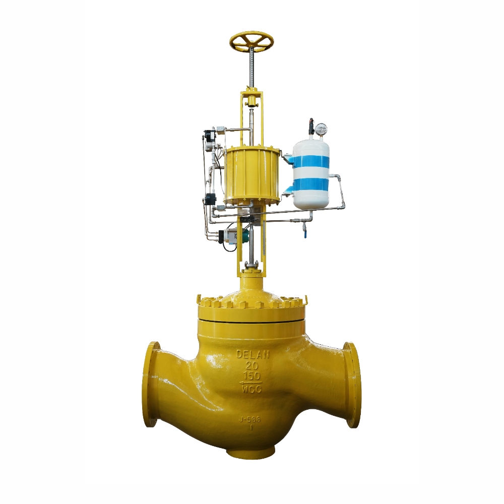
MA Cage Control Valve
The MA Cage-Guided Control Valve is an industrial control valve designed to regulate fluid flow in demanding process systems.
https://www.delan-valve.com/ma-cage-control-valve.html
Product Overview
The MA Cage-Guided Control Valve is an industrial control valve designed to regulate fluid flow in demanding process systems. Its pressure-balanced valve plug, precision cage guidance, and modular trim construction provide stable operation, reliable throttling performance, and convenient maintenance.
Available in globe and angle configurations, the MA series supports a variety of flow characteristics, pressure ratings, trim materials, and connection options. It can be configured for standard flow regulation as well as specialized operating conditions involving high differential pressure, elevated temperatures, noise reduction, and cavitation control.
The valve features a streamlined internal flow path to reduce flow resistance while maintaining high flow capacity. Its replaceable seat and modular internal components also simplify inspection, servicing, and component replacement.
Product Information
| Item | Specification |
|---|---|
| Product Name | MA Cage Control Valve |
| Minimum Order Quantity | 1 Piece |
| Payment Method | T/T (Bank Transfer) |
| Delivery Time | Approximately 60 days for customized products |
| Packaging | Export-standard wooden case |
| Customization | Color, logo, and packaging |
| Manufacturing Services | OBM, OEM, ODM |
| Certifications | ISO 9001, ISO 45001, ISO 14001, CE, EAC |
Main Applications
The MA Cage Control Valve is suitable for flow regulation across various industrial utility and process systems, including:
-
Main Steam Systems
-
Condensate Systems
-
High-Pressure (HP) Heater Drain Systems
-
Low-Pressure (LP) Heater Drain Systems
-
Open-Type Circulating Cooling Water Systems
-
Auxiliary Steam Systems
-
Heater Drain Systems
-
Feedwater Systems
-
Petroleum and Chemical Processing Systems
Key Design Features and Performance Advantages
1. Multiple Flow Characteristics for Different Control Requirements
The standard cage design offers three selectable flow characteristics, allowing the valve to accommodate different process control requirements:
-
Quick Opening
-
Linear
-
Equal Percentage
For specialized applications, additional cage and trim configurations are available, including noise-reduction and anti-cavitation designs.
2. Stable Valve Plug Guidance
The precision cage-guided structure helps maintain accurate valve plug alignment throughout operation. Its robust guiding arrangement minimizes unwanted movement, helping reduce mechanical vibration and operating noise while improving control stability.
3. High Flow Capacity with Reduced Resistance
The internal flow passages are designed with a streamlined geometry to minimize flow resistance. This configuration supports efficient fluid movement and provides high flow capacity for industrial process applications.
4. Pressure-Balanced Plug Construction
The valve plug and cage form a pressure-balanced assembly. This design reduces the influence of fluid pressure differences on valve operation while supporting accurate flow regulation and a wider controllable operating range.
It is particularly suitable for applications involving relatively high differential pressure.
5. High-Temperature Operation and Multiple Shutoff Options
Different sealing arrangements are available to meet varying temperature and leakage-control requirements.
-
Class II and Class III: Standard single graphite piston ring configurations, with shutoff temperature capability up to 593°C.
-
Class IV: Multiple graphite piston rings can provide Class IV shutoff up to 593°C. Elastic energy storage ring configurations are available up to 232°C.
-
Class V: C-seal metal plug sealing arrangements support Class V shutoff up to 593°C. Elastic energy storage ring configurations are available up to 232°C.
The actual shutoff class depends on the selected sealing structure and operating conditions.
6. High-Output Actuation Options
The MA series can be equipped with pneumatic diaphragm or double-acting pneumatic cylinder piston actuators. These actuator configurations provide compact installation and substantial output force for different control requirements.
7. Wear-Resistant Internal Components
Standard hardened stainless steel trim improves resistance to mechanical wear, helping extend component service life under normal operating conditions.
Alternative trim materials and surface treatments can be selected according to fluid characteristics, temperature, corrosion exposure, and pressure differential.
8. Modular Construction for Easier Maintenance
The modular trim arrangement allows internal components to be inspected, serviced, or replaced without complicated maintenance procedures.
The replaceable seat does not require welding or grinding during routine replacement, helping reduce maintenance time and simplify valve servicing.
Valve Construction and Internal Components
The MA Cage Control Valve incorporates a balanced plug, cage-guided structure, replaceable seat, and specialized sealing components to support stable flow regulation and dependable sealing performance.
| No. | Component | Description |
|---|---|---|
| 1 | Double Disc Spring | Provides the spring component within the valve assembly. |
| 2 | Valve Stem | Transmits actuator movement to the valve plug. |
| 3 | Packing | PTFE V-ring packing or graphite packing can be selected according to operating temperature and service conditions. |
| 4 | Middle Flange Gasket | Flexible graphite combined with metal wire reinforcement provides reliable sealing. |
| 5 | Cage | Guides the valve plug and determines the flow characteristic. |
| 6 | Valve Seal (Optional) | Available with an elastic energy storage ring or C-seal ring. |
| 7 | Balanced Plug | Forms a pressure-balanced assembly with the cage. |
| 8 | Replaceable Seat | Replaceable construction eliminates the need for welding or grinding during seat replacement, making inspection and maintenance more convenient. |
| 9 | Seat Gasket | Provides sealing between the seat and the valve body assembly. |
| 10 | Cone Plus Pin | Serves as a locating and connecting component in the assembly. |
| 11 | Balance Hole | Helps balance pressure across the valve plug. |
Technical Specifications
1. Valve Size Range
The MA series covers nominal valve sizes from 1 inch to 16 inches.
| Nominal Diameter | Size (NPS) | DN (mm) |
|---|---|---|
| 1 | 1" | 25 |
| 1-1/2 | 1-1/2" | 40 |
| 2 | 2" | 50 |
| 2-1/2 | 2-1/2" | 65 |
| 3 | 3" | 80 |
| 4 | 4" | 100 |
| 6 | 6" | 150 |
| 8 | 8" | 200 |
| 10 | 10" | 250 |
| 12 | 12" | 300 |
| 14 | 14" | 350 |
| 16 | 16" | 400 |
2. Shutoff Classification and Temperature Capability
The valve supports several leakage-control configurations depending on the selected cage, plug seal, and packing arrangement.
| Shutoff Classification | Sealing Configuration | Temperature Capability |
|---|---|---|
| Class II / Class III | Standard single graphite piston ring | Up to 593°C |
| Class IV | Multiple graphite piston rings | Up to 593°C |
| Class IV | Elastic energy storage ring | Up to 232°C |
| Class V | C-seal metal plug seal | Up to 593°C |
| Class V | Elastic energy storage ring | Up to 232°C |
Available cage and trim configurations include:
-
Equal Percentage
-
Linear
-
Quick Opening
-
Noise Reduction
-
Anti-Cavitation
The original design data also lists the following port diameter options:
| Valve Size | Available Port Diameters |
|---|---|
| 1" | 26 mm |
| 1-1/2" | 26 mm |
| 2" | 58 mm |
| 2-1/2" | 73 mm |
| 3" | 88 mm |
| 4" | 58 mm / 113 mm |
| 6" | 113 mm / 178 mm |
| 8" | 178 mm / 198 mm |
| 10" | 198 mm / 248 mm |
| 12" | 248 mm / 278 mm |
| 14" | 278 mm / 348 mm |
| 16" | 348 mm / 374 mm |
3. Pressure Rating
The MA series is available with several pressure rating options.
| Standard | ANSI Pressure Class | Pressure Rating |
|---|---|---|
| GB/T 9112–9124 | Class 150 | 1.6 MPa / 2.0 MPa |
| GB/T 9112–9124 | Class 300 | 4.0 MPa / 5.0 MPa |
| GB/T 9112–9124 | Class 600 | 6.3 MPa / 10 MPa / 11 MPa |
Final pressure selection should be determined according to the applicable design standard and operating conditions.
4. Valve Body Materials and End Connections
The valve body can be manufactured from carbon steel, alloy steel, or stainless steel to accommodate different process media and operating environments.
Available connection configurations include:
-
RF Flanged Connection
-
RTJ Flanged Connection
-
Butt-Weld Connection
The supplied construction schedule lists the following nominal size groups:
| Valve Size | Available Pressure Classes |
|---|---|
| 1", 1-1/2", 2", 2-1/2" | CL150, CL300, CL600 |
| 3", 4", 6", 8", 10", 12", 14", 16" | CL150, CL300, CL600 |
5. Typical Metal Trim Material Combinations
Different trim material combinations are available to suit normal service, corrosive media, oxidizing environments, high-temperature applications, and other specialized working conditions.
| No. | Plug | Seat | Cage | Stem | Recommended Service |
|---|---|---|---|---|---|
| 1 | CA15 | 410 | CA15 | 410 | General operating conditions; standard WCB valve body |
| 2 | CF3M | 316L | CF3M | 316L | Corrosive service; standard CF8M valve body |
| 3 | CF8 | 304 | CF8 | 304 | Oxidizing service; standard CF8 valve body |
| 4 | CF3M with sealing surface overlay welding | 316L with sealing surface overlay welding | CF3M | 316L | Strongly corrosive service with a certain pressure differential |
| 5 | CF8 with sealing surface overlay welding | 304 with sealing surface overlay welding | CF8 | 304 | Strongly oxidizing service with a certain pressure differential |
| 6 | CF3M with sealing and guiding surface overlay welding | CF3M with sealing surface overlay welding | 630 | 630 | Special operating conditions |
| 7 | CF3M with sealing and guiding surface overlay welding | Stellite 6 | Stellite 6 | 630 | Special operating conditions |
| 8 | WC9 with sealing and guiding surface overlay welding | F22 with sealing surface overlay welding | WC9 | 660 | High-temperature service above 400°C |
Seal ring options for these configurations include elastic energy storage rings and C-seal rings. Final material combinations should be selected according to the process medium and service requirements.
6. Materials of Other Valve Components
The following materials are available for the main valve components and fastening assemblies.
| Component | Material Options |
|---|---|
| Seat Gasket | Flexible Graphite + 316 |
| Internal Parts | A182 F6a / 410; A638 660 / 660; A182 F316H, A182 F316L / 316L, 316H; A182 F304, A182 F304L / 304, 304L |
| Bonnet | WCBNCC / WCBWCC; WC6; WC9; CF8M, CF8 / 304, 304L; CF3M, CF3 / 316L, 316H |
| Packing Seat | A276 410 / 410 |
| Packing | PTFE V-ring; Vermiculite; high-performance flexible graphite; Garlock |
| Locking Nut | A105 |
| Gland | 316L, 304, 410 |
| Gland Flange | 410 |
| Middle Flange Gasket | Flexible Graphite + 316 |
Body-to-Bonnet Bolting
| Component | Standard | Material |
|---|---|---|
| Stud | A193 B16 | 4135 |
| Stud | A193 B8 | 304 |
| Stud | A193 B7 | 4130 |
| Nut | A194 7 | 4135 |
| Nut | A194 8 | 304 |
| Nut | A194 2H | 1045 |
Gland Bush Bolting
| Component | Standard | Material |
|---|---|---|
| Stud | A193 B7 | 4130 |
| Nut | A194 2H | 1045 |
7. Bonnet Selection and Packing Temperature Limits
Plain and extension bonnets are available. The appropriate configuration depends on the packing material and process temperature.
| Bonnet Type | Packing Material | Temperature Range |
|---|---|---|
| Plain | PTFE V-ring | -28°C to 250°C |
| Plain | Graphite ribbon / filament | -28°C to 593°C |
| Extension | PTFE V-ring | -196°C to 250°C |
| Extension | Graphite ribbon / filament | -102°C to 593°C |
Extension bonnets are available for applications requiring different packing temperature arrangements.
8. Trim Materials for NACE MR0175 Sour Service
Material combinations can be configured for sour service applications in accordance with NACE MR0175 specifications.
| Body Material | Plug | Cage | Seat Ring | Stem, Gland, Packing Washer, Stuffing Box Ring, Pin and Bush |
|---|---|---|---|---|
| CF8M | A182 F316 | A182 F316 with electroless nickel coating (ENC) | A182 F316 | A182 F316 |
| WCB | A182 F6a + Stellite | A182 F6a with electroless nickel coating (ENC) | A182 F6a | A182 F6a |
9. Bolting Materials for NACE MR0175 Applications
Bolting materials and temperature capabilities are specified for standard non-exposed and optional exposed bolting configurations.
| Bolting Configuration | Valve Body Material | Fastener | Material | Minimum Temperature | Maximum Temperature |
|---|---|---|---|---|---|
| Standard non-exposed | WCB | Stud | SA-193 B7 | -48°C | 427°C |
| Standard non-exposed | CF8M | Nut | SA-193 2H | — | — |
| Optional exposed | WCB | Stud | SA-193 B7M | -48°C | 427°C |
| Optional exposed | CF8M | Nut | SA-193 2HM | — | — |
The optional exposed bolting arrangement is specified without requiring valve derating in the supplied design data.
10. Globe Valve Dimensions
The following dimensions are provided for the globe-type configuration. Dimensions are in millimeters.
| DN | NPS | Flanged CL150 A | Flanged CL300 A | Flanged CL600 A | BW A | PN16–40 G | PN63–100 G | Globe Type G(MAX) |
|---|---|---|---|---|---|---|---|---|
| 25 | 1" | 184 | 197 | 210 | 210 | 160 | 230 | 60 |
| 40 | 1-1/2" | 222 | 235 | 251 | 251 | 200 | 260 | 71 |
| 50 | 2" | 254 | 267 | 286 | 286 | 230 | 300 | 78 |
| 65 | 2-1/2" | 276 | 292 | 311 | 311 | 290 | 340 | 90 |
| 80 | 3" | 298 | 318 | 337 | 337 | 310 | 380 | 97 |
| 100 | 4" | 352 | 368 | 394 | 394 | 350 | 430 | 129 |
| 150 | 6" | 451 | 473 | 508 | 508 | 480 | 550 | 162 |
| 200 | 8" | 543 | 568 | 610 | 610 | 600 | 650 | 191 |
| 250 | 10" | 673 | 708 | 752 | 752 | 730 | 775 | 250 |
| 300 | 12" | 737 | 775 | 819 | 819 | 850 | 900 | 292 |
| 350 | 14" | 889 | 927 | 972 | 972 | 980 | 1025 | 327 |
| 400 | 16" | 1016 | 1057 | 1108 | 1108 | 1100 | 1150 | 370 |
Related products
-
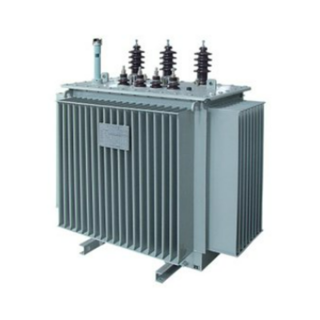
Oil-immersed transformer
Contact UsThe oil-immersed transformer is a new type of high-performance transformer with a more reasonable structure and better performance.
-
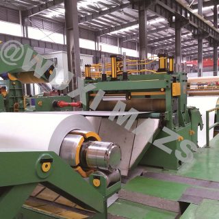
MA-(2~8MM)×1800MM Steel Coil Slitting Line
Contact UsMA-(2~8MM)×1800MM Steel Coil Slitting Line is mainly composed by the following components : uncoiler, guiding device
-

LFQ1300 Micro Computer Controlling Slitting Machine
Contact UsLFQ1300 Micro Computer Controlling Slitting Machine
-

Reviews
There are no reviews yet.